Microwave/RF Filters & Components Simulation
Efficient Simulation of Highly Resonant Structures
RF-Filters and Components
CST Studio Suite technology provides a range of electromagnetic solvers available for the simulation of microwave and radio frequency (RF) filters and components.
RF-Component Simulation in the Time Domain
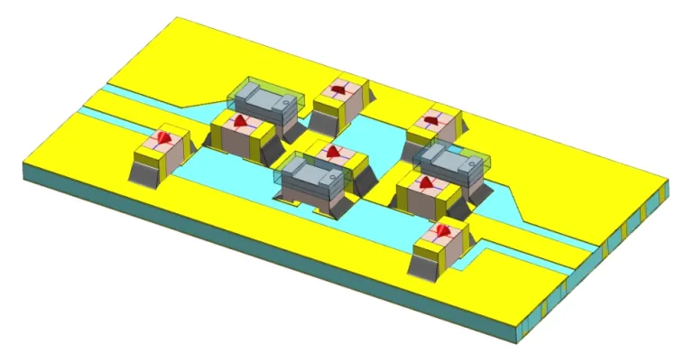
The Time Domain solver is the perfect solution for broadband traveling-wave components like transmission lines and transitions, as well as high-pass/low-pass filters.
Radio-Frequency Filter Design
For highly resonant structures, such as band-pass filters and diplexers, the Frequency Domain solver provides great benefits in terms of simulation accuracy versus speed. Furthermore, it features unique technologies such as the moving mesh, which is important for the mitigation of numerical noise generated by changes in the discretization. It also offers a model order reduction method that is very fast, even in calculating broadband results.
Waveguide ports can be used to excite any type of transmission line and force specific modal distributions. They can also serve as a useful tool in the analysis of transversal modes of arbitrary conducting shapes.
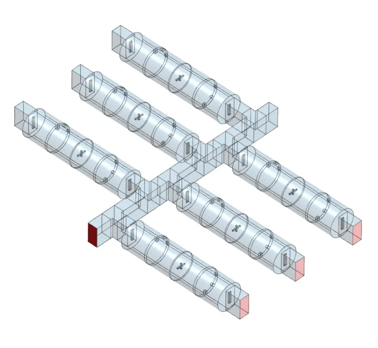
The modeling and analysis of devices with different components or complex building blocks, such as multiplexers, can be simplified using System Assembly & Modeling (SAM). SAM allows for quick assemblies as well as the analysis/optimization of the individual parts within the larger system – for example the feeding network of an antenna. To that end, Fest3D offers dedicated and efficient solver technology for the simulation of waveguide structures.
Passive RF Component Design
- Filter Simulation
- Waveguide Component Simulation
- High-Power Component Simulation
Filter Simulation
Communication networks, in both terrestrial and space applications, are becoming more demanding on the use of the frequency spectrum. To deal with stringent spectrum needs, filters are used. The design and analysis of such devices can be challenging and simulation can play a vital part in the development process. CST Studio Suite offers a range of solutions for different implementations.
FD3D - A Filter Design Tool
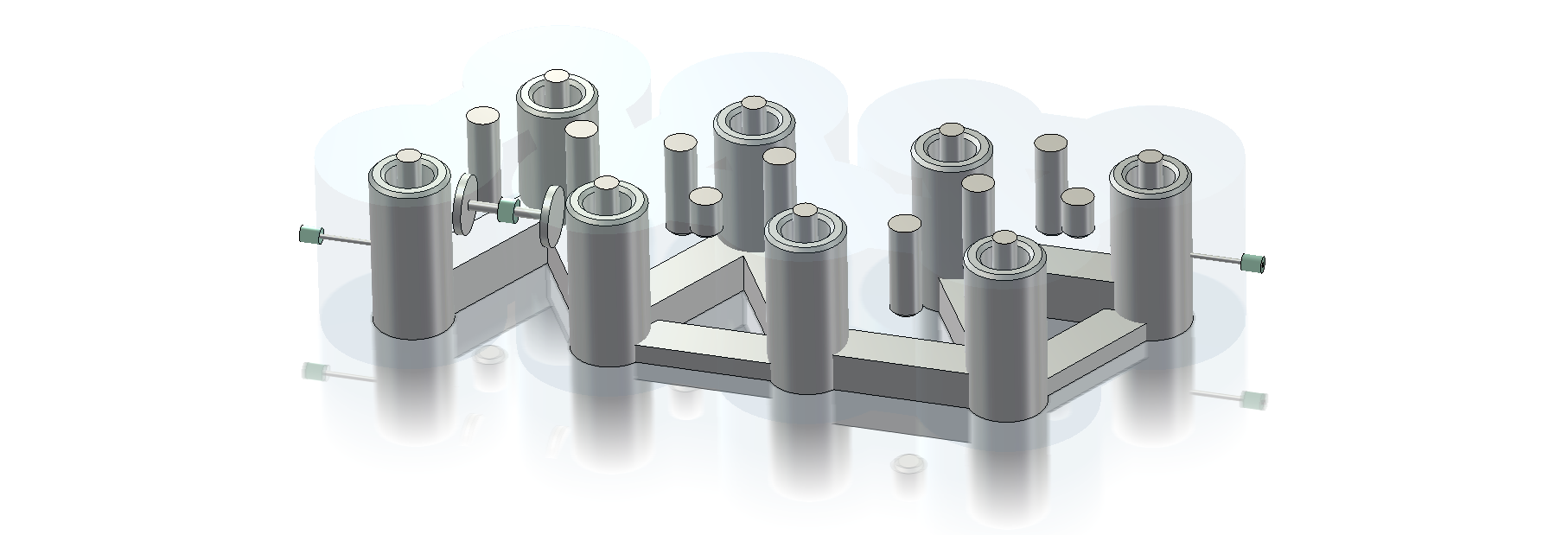
Filter Designer 3D is a general-purpose bandpass filter and diplexer synthesis tool. It uses the well-established coupling matrix synthesis and offers tuning assistance with a robust filter parameter extraction from S-parameters. This technique is also built into a dedicated optimizer for filter models that achieves fast convergence without having to do tedious space-mapping or port-tuning routines. It can even be used on the workbench where hardware can be tuned with the assistance of real-time coupling matrix extraction performed on the measurements.
To go from the filter specifications and synthesis to a fully parameterized 3D model, a range of options is available. With Filter Designer 3D, a general approach is provided that makes use of the component library. The user can either select the different available building blocks or customize it entirely according to their technology requirements. The blocks are automatically assembled according to the synthesized topology to produce a fully parameterized model that includes the optimization setup. For specific waveguide-based low-pass, wideband or dual-mode filters, Fest3D offers design wizards.
Waveguide Filter and Component Simulation
Fest3D provides fast analysis of different components in waveguide technology, which is essential for optimization routines or complex divide-and-conquer workflows. It also provides a model synthesis of dual-mode circular cavities through corrugated waveguide filters. These projects can also be connected in the schematic environment of CST Studio Suite to establish co-simulations with other solver technologies – for example, a waveguide feeding network cascaded with a horn antenna.
Circulator Simulation
Circulator components typically also require coupled simulations where ferrite materials are involved. A static field is required to bias the ferrite that would establish the non-reciprocity, which again is required for the high frequency operation of the circulator. This can be seamlessly achieved in the same environment using a single model in a coupled workflow.
High-Power Component Simulation
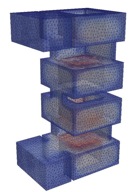
High-power microwave components typically require the analysis of multi-physical phenomena to understand their power-handling abilities. There are always some conducting losses in the device, which lead to thermal heating. The temperature change can cause structural deformation and, finally, it can compromise the electromagnetic performance. In a coupled workflow we can analyze these three physical domains using only a single model for the device.
RF-Breakdown Analysis
RF breakdown is another phenomenon that has the potential to destroy a device. High-intensity oscillating fields have the potential to ionize the gas inside a device, which can cause a corona discharge or, in the absence of gas and, with the presence of free electrons, multipaction. Spark3D provides advanced technologies to calculate these physical domains and demonstrates high accuracy when compared to reliable measurement data.
It is important to take all this into account early in the development process to avoid unforeseen failure of sophisticated or critical components.
Start Your Journey
Explore the technological advancements, innovative methodologies, and evolving industry demands that are reshaping the world of Microwave Filters and Components Simulation. Stay a step ahead with SIMULIA. Discover now.
FAQs About RF-Filter Design
To design an RF-filter, the following steps are typically of relevance:
1. Determine the frequency specifications:
Determine how the frequency range needs to be filtered, by specifying the frequency bands where the signal should be allowed to pass and those that should be rejected, typically illustrated by the S-parameters. This will help in selecting the appropriate type of filter.
2. Choose the filter type:
There are different types of filters such as low-pass, high-pass, band-pass, and band-stop. Each type has its own characteristics and is suitable, as the corresponding names suggest, for a specific response in allowing RF signals. For example, a “band-pass” filtering response is typically used to allow signals through in a specific frequency band, while rejecting everything outside that band.
3. Select the filter topology:
A topology is typically some type of circuit layout that would realize the desired filtering response. This can come in the form of a ladder inductor and capacitor (LC) circuit, or in the band-pass case, it is commonly in the form of coupled resonators.
4. Calculate component values:
The filter topology can be synthesized using various mathematical methods or filter design software. With that the required values for the components like resistors, capacitors, and inductors are calculated.
5. Realize RF-circuit design:
Once this ideal circuit is designed, it must be realized in some manufacturable medium. One approach is to use discrete inductor and capacitor (LC) components and implement the topology as-is. However, as the frequency of interest increases, this approach becomes less appropriate. The parasitic effects from components and inter-connects will become very large and at some point, the filtering characteristics can no longer be achieved. Therefore, another approach is to implement the circuit in a distributed form, using microstrip, waveguides or other high frequency technologies.
6. Simulate and optimize the design:
Before finalizing the designed model, simulation will be required to verify the filter’s performance. It is also very common to apply tuning or optimization in the EDA environment, to achieve the required frequency specifications. Other aspects that can be of interest during the simulation phase are the thermal or RF-breakdown effects – especially with high-power devices.
7. Build a filter prototype:
Once satisfied with the simulation results, build a physical prototype and test it under various conditions to validate its performance.
8. Fine-tuning of the filter:
If there are any discrepancies between simulation results and real-world measurements, fine-tune the component values accordingly until desired specifications are achieved. For that, one option may be to use computer-aided tuning provided by advance software tools.
Radio frequency (RF) filters refer to electronic devices that are designed to allow or block signals, depending on its frequency components. They are commonly used in a wide range of wireless (and wired) applications, where commercial communication systems are perhaps better known – such as radio, television, cellular and GPS networks. Here are some of the basic concepts of RF filters:
1. Filtering technology:
There are different types of RF filters, each using different technology mediums that depends on the frequency range, physical size, manufacturing cost and power handling. These include various types of waveguides, ceramics, printed circuit boards, integrated circuits and even piezoelectric crystals.
2. Filter design:
The design of an RF filter depends on its application and the specific frequency range that must be filtered. Some common types include low-pass, high-pass, bandpass, and band-stop filters. These can be synthesized using various techniques that involve circuit theory (for example ladder circuits) and applied mathematics (for example coupling matrices).
3. Frequency response:
The frequency response of an RF filter refers to how it behaves with respect to different frequency components of a signal that is being applied. The ideal band-pass filter should have a flat frequency response without ripple in the allowed band with minimal phase distortion, while attenuating all other frequencies.
4. Impedance Matching:
For optimal performance, RF filters need to be impedance-matched to the source and load circuits they are connected to, ensuring optimal power delivery with reduced signal reflections.
5. Insertion loss:
Every filter introduces some amount of loss in the filtered signal. This is known as insertion loss and is measured in decibels (dB). A lower insertion loss means higher efficiency for the system link budget.
6. Bandwidth:
Bandwidth refers to a continuous range of the frequency spectrum typically illustrated through S-parameters.
7. Selectivity:
Selectivity is a measure of how well an RF filter can discriminate between desired and undesired signals within a specific frequency range. The steeper the roll-off of the attenuation slopes, the higher its selectivity. The order of the filter typically influences the selectivity.
8. Applications:
RF filters have various applications in communication systems, including signal separation, interference rejection, harmonic suppression, channel selection, and spectral purity.
1. Band-pass filter:
This type of filter allows only a specific frequency band to pass through while attenuating all other frequencies. It is commonly used in radios and communication systems.
2. Low-pass filters:
A low-pass filter allows frequencies below a certain cut-off point to pass through while attenuating higher frequencies. It is commonly used to remove higher-order harmonics.
3. High-pass filter:
A high-pass filter allows frequencies above a certain cutoff point to pass through while attenuating lower frequencies. It is commonly used to remove low-frequency noise from signals.
4. Notch filter:
A notch filter attenuates a specific frequency or extremely narrow band of frequencies while allowing all others to pass through. It is commonly used in radio frequency interference (RFI) mitigation.
5. Stop-band filter:
This type of filter attenuates only a specific frequency band while passing all other frequencies. It is commonly used in applications where unwanted signals need to be removed.
6. Tunable filters:
These filters allow the user to adjust the cut-off frequencies of the filtering response according to their needs, making them suitable for various applications such as signal processing and testing.
Also Discover
Learn What SIMULIA Can Do for You
Speak with a SIMULIA expert to learn how our solutions enable seamless collaboration and sustainable innovation at organizations of every size.
Get Started
Courses and classes are available for students, academia, professionals and companies. Find the right SIMULIA training for you.
Get Help
Find information on software & hardware certification, software downloads, user documentation, support contact and services offering