
IVCAD Suite Measurement Standard
Conduct advanced tests on RF transistors for model extraction, begin passive load pull measurements, and test and linearize RF power amplifiers.
Measure RF Transistors and Amplifiers
IVCAD Measurement Standard (IVT) offers advanced DC and RF measurement capabilities, such as synchronized pulsed IV and S parameters, allowing for the subsequent extraction of transistor models. To validate these models, load pull measurement data is required. IVCAD offers the most advanced industrial measurement solution for tuner control, enabling impedance sweeping and characterization in nonlinear conditions, while controlling a wide variety of test configurations (scalar or vector benches, harmonic control, etc.).
This module also allows for easy circuit measurement under various test conditions, with modulated signal control and digital predistortion functions to reveal the maximum performance of power amplifier circuits.
IVCAD Suite Measurement Standard - IVT
- Pulse IV and S-Parameter Measurements
- Load Pull Measurements
- Intermodulation and Spurious
- IQ Mod/Demod & DPD Control
A Game-Changer for GaN Transistor Characterization
IVCAD Suite Measurement Standard (IVT) reshapes Pulsed IV measurements with the powerful AMCAD SAS’ Pulsed IV test system.
The current-voltage (IV) measurements play a crucial role in understanding how input and output currents and voltages interact in a device. For GaN Field Effect Transistors (FETs), this involves measuring output current based on varying input voltages, offering key insights into device performance.
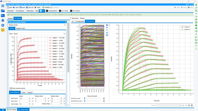
Because of their ability to deliver high power, GaN devices are prone to self-heating and trapping effects, making careful voltage pulsing critical. By pulsing voltages between quiescent and hot values and adjusting pulse-widths, the average power delivered to the device is reduced, minimizing self-heating. This technique ensures near-isothermal performance, enabling more accurate and efficient testing.
IVCAD also enables the detection and visualization of trapping phenomena, such as gate and drain lag, in GaN transistors. It’s easy to observe how trapping effects evolve with different quiescent bias levels. Additionally, it supports full wafer control through seamless integration with various probe station software.
Synchronize Pulse IV and Pulse S Parameters
Unlike traditional S-parameters, which are measured under static conditions, Pulsed S-parameters can provide invaluable information to extract the equation parameters used for transistor compact modeling.
RF transistors, such as those in power amplifiers, often experience significant temperature variations and power fluctuations during operation. Traditional, continuous S-parameter measurements fail to capture the true performance of these devices under dynamic operating conditions when a large RF signal is applied across the IV current source.
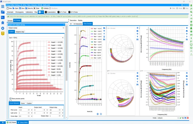
Pulsing the input signal allows engineers to observe the transistor’s response for quasi-isothermal conditions, which enable an electrothermal description of the transistor behavior, and to extract nonlinear equations such as nonlinear capacitances.
These measurements are crucial because Pulsed S parameters reveal the transient effects that occur when RF transistors are driven hard, including the impact of self-heating, and other nonlinear behaviors. Without pulsed testing, engineers risk missing critical performance degradation that can affect device efficiency, reliability, and longevity
A Key Technique for Accurate RF Transistor Characterization
Load Pull is an essential technique for characterizing RF transistors, especially when operating in the nonlinear or large-signal region. S parameters provide valid results only in the linear region, where RF transistors are inefficient and output minimal power.
Load Pull accurately measures devices under real-world, high-power conditions, making it the preferred choice for assessing transistors in RF Power Amplifier applications. When a transistor operates with a large signal, Load Pull is the only reliable method to simulate application-like conditions and predict key RF specifications.
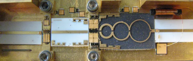
Make It Simple with Few Hardware
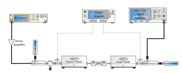
Traditional Load Pull, or Scalar Load Pull, was the first system to measure device performances automatically under various source and load impedances. The scalar setup can use coaxial or waveguide tuners. These test benches use pre-characterized passive tuners for impedance matching and scalar power detectors for measurements. Based on the pre-characterization of the impedance tuners, the measurements rely on the set of measured or interpolated s-parameters at different impedance conditions.
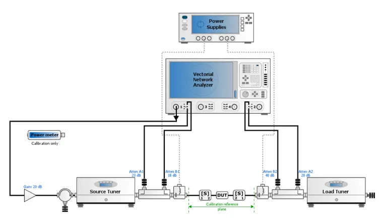
Use a Vector Network Analyzer for Nonlinear Characterization
With the advent of new Vector Network Analyzer technologies, device characterization benches shifted to Vector Receiver Load Pull (VRLP) for a much more complete characterization technique. It allows extracting parameters not possible to measure with a Scalar Setup, like AMPM curves. Therefore, most of the load pull setups built nowadays are Vector based.
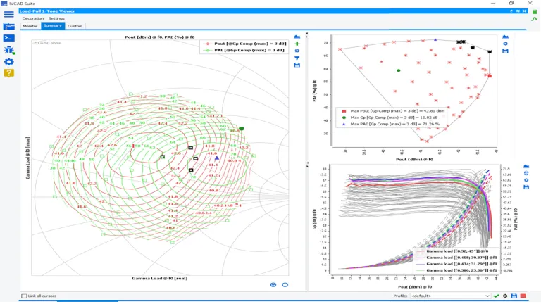
Find a Needle in a Haystack
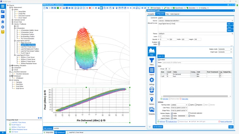
Load Pull measurement data can be challenging to handle for several reasons, primarily due to the complexity of the measurements themselves and the need for precise interpretation of the results.
Load Pull testing involves sweeping various parameters (such as frequency, power, impedance, and bias conditions) and can generate large datasets. Finding the key information among this huge quantity of data that can be overwhelming. Incorrect analysis can lead to misleading conclusions about the transistor's performance.
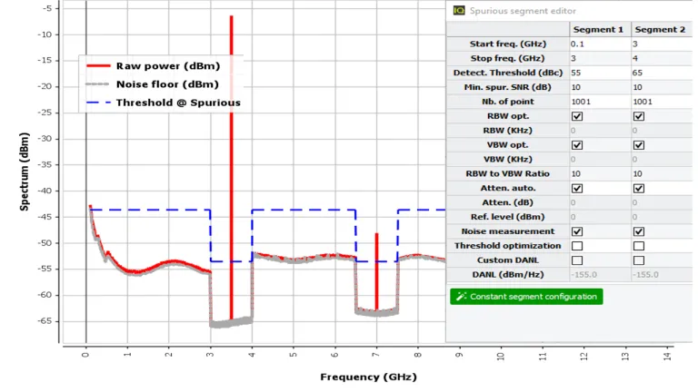
Quickly Detect Unwanted Tones
The Fast Spurious detection mode is provided with scalar or vector setups. It enables Spurious detection using a spectrum analyzer, or a VNA equipped with spectrum software options. This module allows a fast search and analysis of spurious signals, using the spectrum analyzer to recover the trace for each swept parameter.
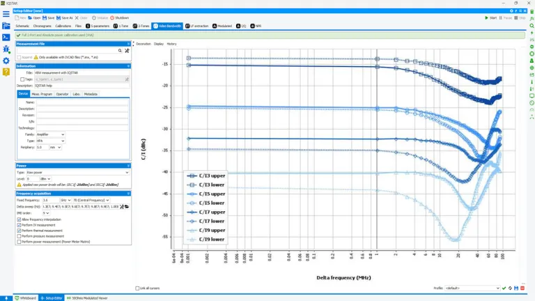
Can Your Amplifier Be Linearized Using its Video Bandwidth?
In addition with harmonic measurements, using two combined analog RF sources or one vector signal generator, a spectrum analyzer, or a vector network analyzer with frequency offset options, IVCAD IVT guides you through a simplified calibration procedure and provides high measurement accuracy needed for 2-tones measurements and Intermodulation (IMD) products.
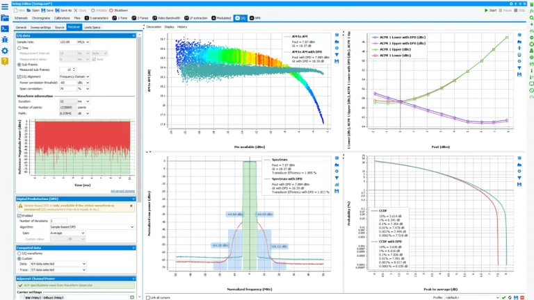
Take Control of IQ Data
Once the Video bandwidth of the power amplifier is known, IVCAD IVT can use IQ values sent to the Vector Signal Generator (VSG) and fetched from the Vector Signal Analyzer (VSA). The IQ data is resized, realigned, and analyzed to extract user-selected parameters (ACPR, CCDF, PAPR, Dynamic AMAM…). With this option, the VSA does not need any specific software options, the application aligns the IQ signals at the input and the output and extract all requested parameters.
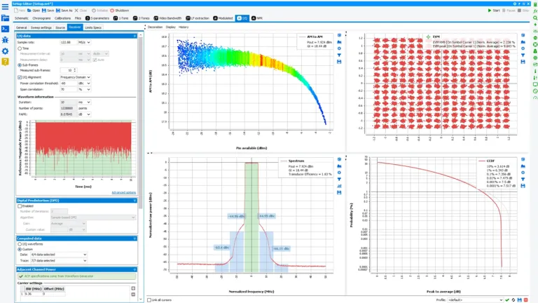
Demonstrate the Power Efficiency of Your Circuits Once Linearized
Power Amplifiers are inherently nonlinear components in a communication systems and are the most critical components. The nonlinearity generates spectral regrowth, which leads to adjacent channel interference and violations of the out-of-band emission requirements. The nonlinearity also causes in-band distortion degrading the bit error rate (BER) performance.
Also Discover


Learn What SIMULIA Can Do for You
Speak with a SIMULIA expert to learn how our solutions enable seamless collaboration and sustainable innovation at organizations of every size.
Get Started
Courses and classes are available for students, academia, professionals and companies. Find the right SIMULIA training for you.
Get Help
Find information on software & hardware certification, software downloads, user documentation, support contact and services offering