
IVCAD Suite Measurement Specialized
Waveguide measurement setups ctrl, Active Load Pull measurements, Data generation for advanced component and circuit modeling
Innovate through Specialized RF Measurements
To further explore circuits' performance, IVCAD Measurement Specialized complements the standard measurement workflow with more advanced test features.
Passive impedance tuners may not be sufficient to cover the entire Smith Chart with the desired load impedances due to inherent losses between the tuner and the device. Active and hybrid load pulls combine active and reflected power waves toward the component to leverage the capabilities of load pull benches.
Specific measurement methodologies have been developed to reveal the low-frequency memory effects of power amplifiers caused by the non-constant envelope of modulation signals, such as those in 5G NR. These methods involve scanning the tone spacing between the probe and carrier frequencies, allowing for accurate modeling of RF circuit behavior under realistic operating conditions.
In addition, test setups made of high-frequency waveguide test accessories may require a specific calibration process and measurement routines. This module guides users step-by-step for accurate device characterization.
IVCAD Suite Measurement Specialized - IVZ
- Pre-RF Pulse IV Measurements
- Active and Time-Domain Load Pull
- 2-Tone Phase Coherent Tests
- Control of Waveguide Setups
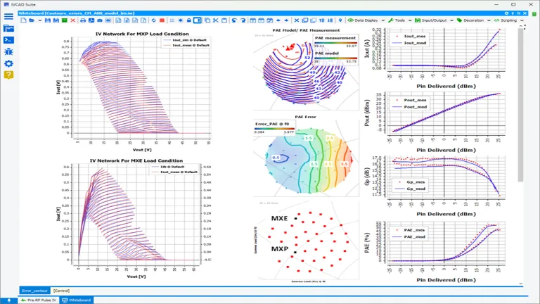
Reveal Actual Pulse IV Curves as a Function of Trap Level on GaN Transistors
GaN transistor models are typically extracted from pulsed IV and S-parameter measurements for different quiescent bias points and temperatures. A transistor tested with these short pulsed IV signals and low-power RF measurements will not behave the same if this one is driven by a power signal, as it will experience different impedances under nonlinear conditions.
Therefore, extracting a single model that accurately represents these different test conditions is not straightforward.
To streamline this process and avoid time-consuming and painful modeling, a specialized measurement methodology has been developed. This method involves measuring the pulsed IV curves on a transistor immediately after it is briefly illuminated by a power RF signal under controlled saturation and load impedance conditions.
This approach provides a set of IV curves that reflect the transistor's realistic behavior when amplifying an RF signal under realistic test conditions at the frequency of interest.
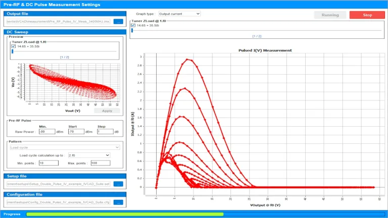
Synchronize Pre-RF Pulse and Pulse IV Measurements
Under fixed load impedance conditions, when the component is biased to its nominal quiescent value, a pre-RF signal is provided to trigger potential trapping effects in the GaN transistor, which impacts the IV pulse measurement performed immediately after this illumination.
Using a VNA based on IVCAD's load pull, an equivalent conversion of the a and b waves measured during the RF pulse is performed to calculate the equivalent voltage waves. These waves, discretized over a period of the periodic RF signal, generate a table of input and output voltage values reused by the IV pulse measurement test instrument immediately after RF illumination.
These equivalent input and output voltages measured by the AMCAD Pulse IV system thus provide a snapshot of the transistor's IV pulse curves when loaded by a load impedance, for different saturation levels.
These IV pulse measurements can then be easily integrated into the intrinsic reference plane of the transistor’s current source for accurate and accelerated modeling flow using IVCAD Suite Modeling(IVM) tool.
Change the Impedance Using Active Load Pull Source
Active Load Pull is a technique using active power injection to synthesize a reflection coefficient at the DUT reference plane. The power injection can be supplied using signal generators and power amplifiers.
Active Load Pull module allows control of the reflection coefficient at the load side (ΓL) as the ratio between the reflected (a2) and forward (b2) traveling waves at the output of the DUT. A generalized form of the formula can be written as ΓL = (a2/b2). The wave b2 is taken as the wave coming from the device, while a2 is the reflected wave seen by the device under test, coming either from a passive circuit, an active circuit or a combination of both for hybrid load pull.
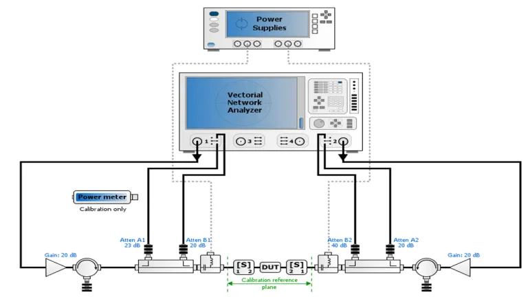
Active injection load pull relies on external sources (with phase and amplitude control enabled) to inject a signal toward the DUT, thereby creating the appropriate a2. Because a2 is no longer limited to a fraction of the original reflected signal, external amplifiers may be used to increase the amplitude of a2 so that ΓL can even achieve unity.
Unlike harmonic passive tuners, perfect isolation can be achieved between fundamental and harmonic load tuning, which is important when the load at the fundamental frequency mainly drives performances.
Combine Passive & Active Loads
Unlike passive harmonic tuners, active load pull provides perfect isolation between the fundamental and harmonic load tuning, which is important when the load at the fundamental frequency primarily influences performance. However, active load pull requires power amplifiers to amplify the reflected signal to the device under test, which can be costly.
Combining the two approaches (active and passive) reduces the required RF power while removing the barriers of passive tuners.
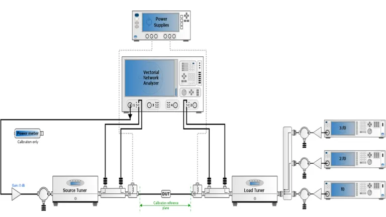
Hybrid active load pull is a technique that uses both passive tuners and active injection. This method limits the need for a high-power amplifier for active injection by pre-matching the device using the passive tuner. This technique is a good compromise when high gamma is required at the reference plane of the device under test, but the active injected power is limited.
Furthermore, the combination of reflected signals sent by the passive tuner and active RF sources can be tuned for either fundamental or harmonic frequencies. This technique is often used to transform a load pull to control load impedances at fundamental frequencies only into a harmonic load control solution.
Shift from Frequency to Time Domain
Nonlinear time-domain signal analysis (LSA) is performed by waveform reconstruction, based on the inverse Fourier transform, which recombines the a and b waves to reproduce the original RF signal as a function of time.
This configuration requires a calibrated harmonic comb generator, such as the AMCAD-SAS HPR727A Harmonic Phase Reference Module, to calibrate the phase relationship between the different harmonic frequencies. Therefore, the LSA functionality allows plotting voltage and current waveforms and displaying dynamic load lines for each measurement state (impedance/power/bias). All measurements are de-embedded within the device's reference plane.
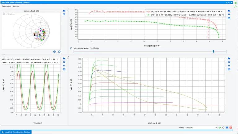
Used in conjunction with the linear transistor model description provided by IVCAD SUITE MODELING (IVM), these waveforms can be de-embedded further beyond the measurement plane, in order to observe in real time the technical impact of the waveform obtained by controlling the harmonic load impedances in the reference plane of the transistor current source, as a designer would do in simulation.
Such measurements can also be used to create an EPHD behavioral model of the DUT provided by IVCAD (IVM) dedicated to harmonic balance simulations in circuit simulators.
Reveal Low Frequency Memory Effects in Power Amplifiers
Low-frequency memory effects in power amplifiers refer to the phenomenon whereby the amplifier's instantaneous response depends not only on the current input signal, but also on its past values. These memory effects occur at frequencies below the amplifier's operating carrier frequency.
These effects can be triggered by variations in the signal envelope amplitude, creating dynamic self-heating, electron trapping and de-trapping, or low-frequency bias modulations.
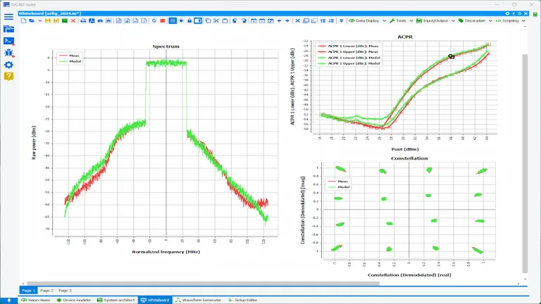
These memory effects can increase signal distortion and reduce the amplifier's overall efficiency. In addition, incoherent gain and altered linearity can also be observed.
It is therefore crucial to extract the time constants of these memory effects in order to integrate them into the behavioral model of the circuit under test if this model is to be used later for a simulation of the system transmitting modulated signals.
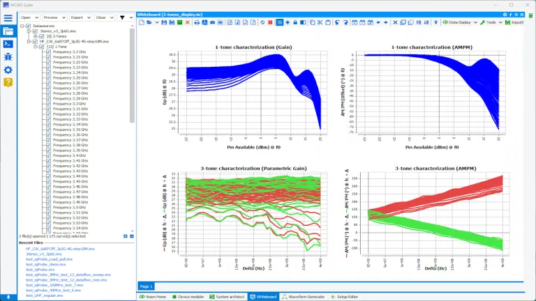
Probe the Long and Short Term Memories, and Their Mutual Dependencies
IVCAD (IVZ) provides control of a test bench based on a vector network analyzer, handling tone spacing sweep and amplitude control of a two-tone phase-coherent signal to extract amplifier behavioral models incorporating the following effects:
- Bilateral effects related to variable load impedance;
- Low-frequency memory effects related to the envelope of modulated signals;
- High-frequency memory effects related to the carrier frequency value.
Such a behavioral model is extracted using the IVCAD Suite (IVM) modeling module, dedicated to circuit behavioral modeling and system simulation.
Run Millimeter Wave Measurements
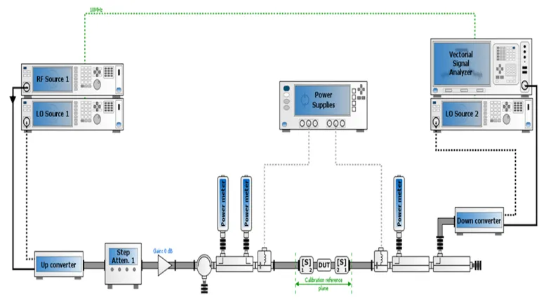
The IVCAD Suite Measurement Specialized (IVZ) suite allows you to control a scalar waveguide test bench and characterize the device under test using a signal generator, power meters, up- and down-converters, and controllable step attenuators.
Various frequency conversion configurations are available, allowing the user to control the up and down-converter. These ones can be configured in mixer or multiplier/divider mode, providing great flexibility in configuring the local oscillator source.
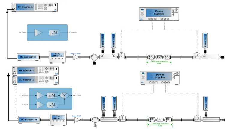
In a waveguide configuration, the power level is controlled by an external step attenuator to avoid nonlinearities generated by the up-converter. Two or three power sensors can then be used to measure Pin, Pout, and Prefl, extracting additional parameters such as IRL, delivered Pin, and Gp at millimeter-wave frequencies.
Control the Envelope Modulation Carried by a Millimeter Wave Frequency
Waveguides introduce insertion losses due to their material properties, and reflections can occur in the event of mismatches between components. These losses and reflections can be frequency-dependent and difficult to model accurately, especially at high frequencies.
It is, therefore, essential to properly manage the assembly of components used on the test bench and perform accurate calibration to generate reliable data, particularly for the measurement of modulated signals, where monitoring in the component's reference plane poses an additional challenge.
With IVCAD (IVZ), the device under test can be characterized using a complex RF signal carried at millimeter-wave frequencies to measure various figures of merit related to the excitation of a modulated signal.
IVCAD retrieves the main figures of merit provided by the vector signal analyzer in a wideband signal configuration, such as ACPR, CCDF, and PAPR, for a configuration built around waveguide components.
Also Discover


Learn What SIMULIA Can Do for You
Speak with a SIMULIA expert to learn how our solutions enable seamless collaboration and sustainable innovation at organizations of every size.
Get Started
Courses and classes are available for students, academia, professionals and companies. Find the right SIMULIA training for you.
Get Help
Find information on software & hardware certification, software downloads, user documentation, support contact and services offering