Antenna Magus Calculators
Antenna Magus Toolbox for Simplified Antenna Design
The Antenna Magus Tool Box
The Antenna Magus Toolbox contains a collection of useful tools and utilities for Antenna designers to simplify everyday antenna tasks. We group these tools according to Antenna Properties, System calculators, Approximation tools, Data conversion tools, General Properties and Transmission Line Calculators.
- Data Conversion
- System Calculators
- Transmission Line Calculators
- Antenna Properties
- Reflectors
- General Properties
Chart Tracing Tool
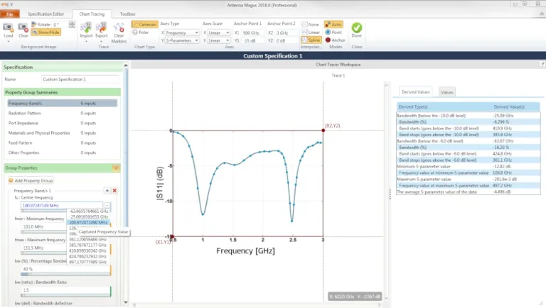
The Chart Tracing Tool is probably one of the most useful utilities in Antenna Magus. It started as an in-house application used by the engineers to read off design values from scanned graphs, mostly from published papers that were only available in *.pdf or in hardcopy. After showing the tool to other engineers and seeing their excitement, we decided to include it as a utility in Antenna Magus.
Simply select your scanned graph image, specify anchor values and follow the traces with your mouse. Apply the spline or linear function and export the XY-values to a Tab Separated Values (TSV) file. It supports both polar and cartesian graphs.
The Chart Tracing tool automatically extracts values relevant to the indicated data type, making it easy to determine quantities such as bandwidth, sidelobe level etc. of the data. You can use these values for design or specification refinement.
Read more about how to use the Chart Tracing Tool.
Angle Conversion Calculator
This calculator converts angular values between different unit types. The table shows the factors used to convert to degrees.
| Convert from | Multiplication factor |
| Degree | 1 |
| Radian | 180/π |
| Gradian | 360/400 |
| Minutes | 1/60 |
| Seconds | 1/3600 |
| Milliradians | 180/(1000*π) |
| Revolution | 360 |
Length Unit Conversion Tool
This calculator converts length values between different unit types. The table shows the factors used to convert to meters.
| Convert from | Multiplication factor |
| Micrometer | 1e-6 |
| Micron | 1e-6 |
| Millimeter | 1e-3 |
| Centimeter | 1e-2 |
| Meter | 1 |
| Kilometer | 1e3 |
| Mil | 25.4e-6 |
| Inch | 25.4e-3 |
| Foot | 0.3048 |
| Yard | 0.9144 |
| Mile | 1609.344 |
dB-V-P Ratio Tool
The equation shows the relationship between a decibel value and a linear voltage/power ratio. You can use this calculator in one of three ways:
- Specify decibel values and the calculator returns the linear voltage and power ratios
- Specify a linear voltage ratio and the calculator returns the decibel value together with the linear power ratio.
- Specify a linear power ratio and the calculator returns the decibel value together with the linear voltage ratio.
dB = 20log10(voltage ratio) = 10log10(power ratio)
Two-Port Network Conversion Tool
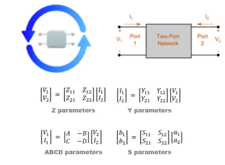
This calculator allows the conversion between various two-port parameters. The two-port parameters include Z (impedance), Y (admittance), ABCD-parameters (chain) and S-parameters (scattering).
Most microwave textbooks [for example Pozar] provide useful conversion formulas to switch between various two-port parameter conventions. However, the books often only provide conversions for simplified cases. Specifically, where the impedance values of port 1 (source) and port 2 (load) are real, equal, or where a common port and system impedance is enforced.
This calculator allows for the impedance of the two ports to be complex and unique using the equations developed by Dean Frickey. The image shows a standard two-port network and basic two-port equations.
VSWR Return Loss Calculator
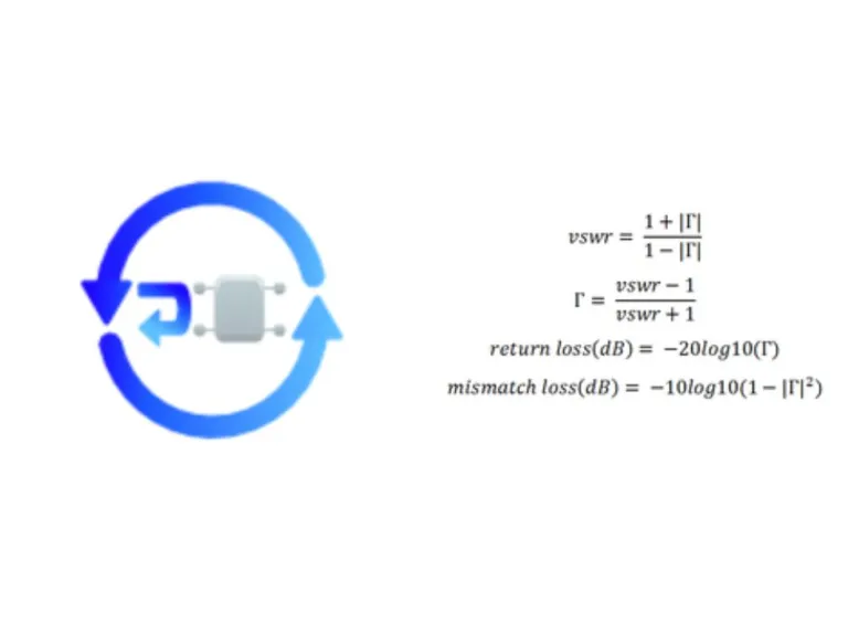
The Voltage Standing Wave Ratio (VSWR), reflection coefficient (Τ), return loss and mismatch loss depend on one or the other, as we can see by the equations.
This calculator consists of four design groups. Each group requires one objective input and returns the remaining three.
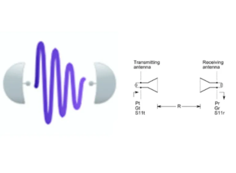
Friis Transmission Equation Calculator
This calculator solves the Friis transmission equation for any of its variables. The Friis transmission equation relates the power received by an antenna to the power radiated by another antenna, a specified distance away (in free space). Modified forms of the basic Friis equation allow for inclusion of many system factors, including antenna mismatch, absorption in the propagation medium, cable loses, etc. The Antenna Magus calculator includes antenna mismatch effects. It does not compensate for polarization and physical misalignment, but can consider them by adjusting the figures used for the gain of the respective antennas.
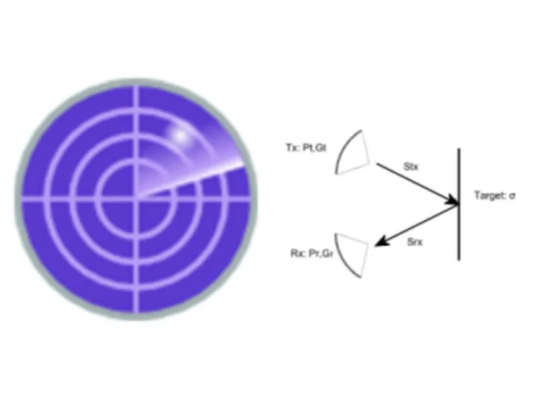
Radar Range Equation Tool
This calculator solves the well-known Radar range equation for any of its variables. The Radar range equation relates the power received by the radar receiver to:
- The power transmitted by the radar transmitter,
- The radar cross section of the target,
- The gains of the antennas,
- The frequency and
- The distance between the antennas and the target.
The form of the equation used in this calculator allows for bi-static radar, but does not consider polarization mismatch or gain compensation for misaligned antennas
Signal to Noise Ratio Tool
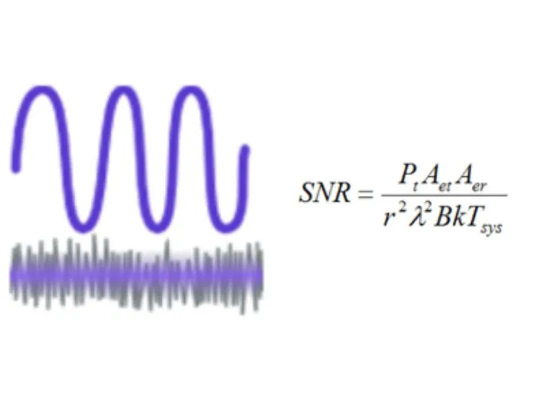
The signal-to-noise-ratio (SNR) is a criterion of detectability in a communication link. In basic terms, it compares the level of the required signal to the level of background noise. A ratio more than 1:1 indicates more signal than noise.
The equation used in this tool is show here. The parameters used in the equation are:
- Transmitted power (Pt),
- Transmitter antenna effective aperture (Aet),
- Receiver antenna effective aperture (Aer),
- Transmitter-receiver distance (r),
- Wavelength (λ),
- Bandwidth (B),
- Boltzmann constant (k)
- System temperature
For example, the following input parameters result in a signal-to-noise ratio (SNR) of 72.78e-3.
- Transmit power: 1 mW
- Operating frequency: 1 GHz
- Effective transmitter antenna aperture (AET): 78.53 cm2
- Effective receiver antenna aperture (AER): 100 cm2
- Antenna separation: 10 km
- System bandwidth: 30 MHz
- System temperature: 290 K
Passive Remote Sensing Tool
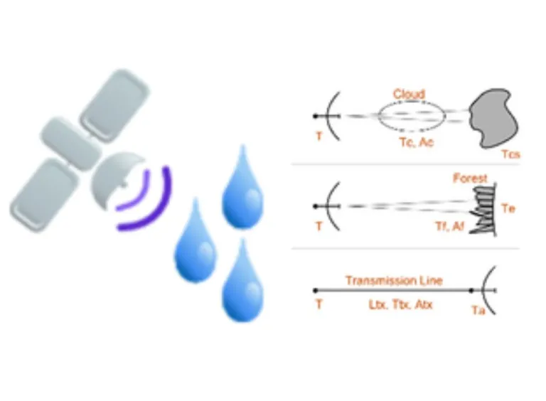
Radio telescopes are remote sensing devices. Earth-based telescopes point at the sky for observing celestial objects. Telescopes installed on aircraft or satellites point at the earth. The equation assumes that the radiation detected or sensed by the telescope originates in the observed objects, known as passive remote sensing.
This tool calculates the temperature (measured or that of the object) for various remote sensing applications:
- Earth-based radio telescope remote-sensing celestial source through interstellar cloud
- Radio telescope on satellite remote-sensing the earth through forest
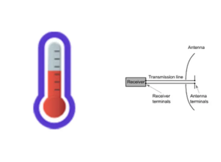
- Receiver detecting antenna output through transmission line
System Temperature Calculator
The antenna is part of the receiving system consisting, in general, of an antenna, a receiver and a transmission line, which connects them. The temperature of the system is a critical factor in determining the sensitivity and signal-to-noise ratio of a receiving system.
The equation used in this tool is:
The parameters used in the equation are:
- Antenna noise temperature in Kelvin (Tan)
- Physical antenna temperature in Kelvin (Tap)
- Antenna efficiency (Ea),
- Physical transmission line temperature in Kelvin (Tlp)
- Transmission line efficiency (El)
- Receiver noise temperature in Kelvin (Trn)
to yield a system temperature in Kelvin (Tsys).
Communication Downlink Calculator
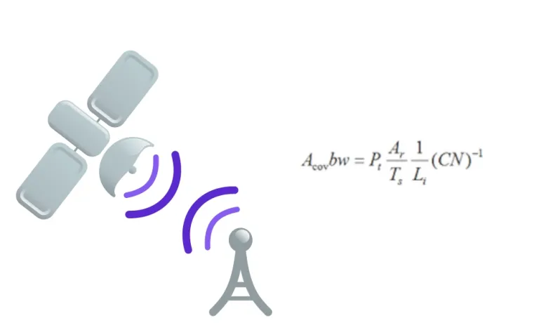
A communication satellite functions as a radio relay in space. The communication link can be between stations on earth, or between antennas from other satellites.
One way to increase the capacity of the system is to increase the bandwidth (bw). Frequency reuse is one way to increase bandwidth. In cases with fixed carrier-to-noise power ratio (CN), the reduction of the coverage area (Acov) can increase bandwidth. Multibeam antennas can reduce the coverage area, because they divide power among the beams.
Other parameters of the equation include the satellite transmitter power (Pt), earth station antenna affective area (Ar), equivalent system temperature (Ts) and incidental loss (Li).
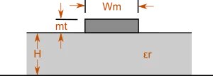
Microstrip Line
This calculator determines the electrical characteristics for the given physical properties of a microstrip line, or vice versa. The calculations consider the effect of the metal thickness.
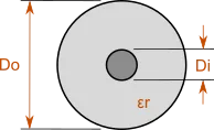
Coaxial Cable
This calculator determines the impedance for a specified physical coax, or it calculates the inner or outer diameter for the given parameters. It also calculates other transmission line parameters such a capacitance and inductance per unit length.
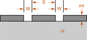
Coplanar Waveguide
This calculator determines the electrical characteristics for the given physical properties of a coplanar waveguide structure, or vice versa. The calculations consider the effect of the metal thickness.
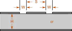
Grounded Coplanar Waveguide
This calculator determines impedance for the given physical properties of a grounded coplanar waveguide structure
Circular Waveguide
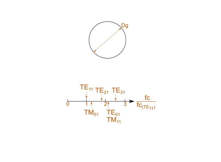
This calculator determines the cutoff frequency, wave impedance and the guided wavelength of the first five dominant modes for the defined circular waveguide.
The fundamental mode of operation in a circular waveguide is the TE11 mode. We show a representation of the relative cutoff frequencies, normalizing the frequencies to the fundamental TE11 mode’s cutoff frequency.
Rectangular Waveguide
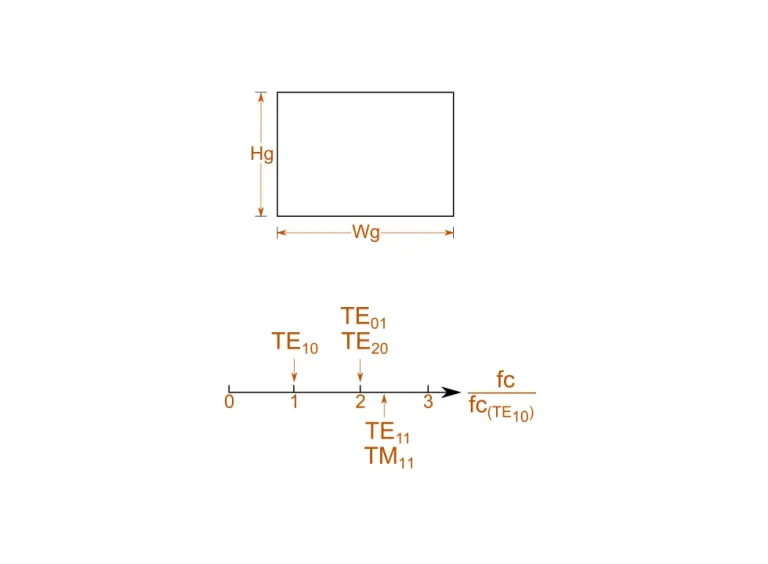
This calculator determines the cutoff frequency, wave impedance and the guided wavelength of the first five dominant modes for the defined rectangular waveguide.
The fundamental mode in a rectangular waveguide is the TE10 mode. In this mode, the impedance of the waveguide is entirely dependent on the width of the waveguide. We show a representation of the relative cutoff frequencies, where normalizing the frequencies to the fundamental TE10 mode’s cutoff frequency.
Gain / Beamwidth Converter
This calculator calculates an approximate gain for given beamwidths, or vice versa. The exact gain depends on many factors, but this handy calculator provides a useful rule of thumb guideline. The calculator allows the specification of both the vertical and horizontal beamwidths separately.
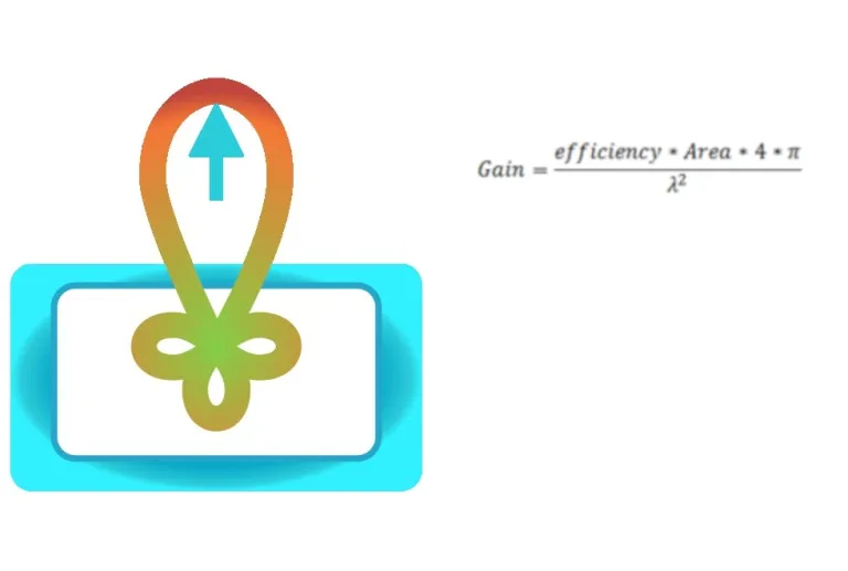
Gain from Aperture
This calculator calculates the expected gain for an aperture of a given area and efficiency. It can also invert the equation to solve for any of the other parameters. For instance, it calculates the aperture efficiency of a horn antenna.
Antenna Efficiency Tool
The total antenna efficiency considers losses at the input terminals and within the structure of the antenna. Typical losses are:
- Reflections due to the mismatch between the transmission line and the antenna
- I2R losses (conduction and dielectric)
This tool calculates the total antenna efficiency using the following equation:
e0 = er ecd
where
e0 = total antenna efficiency
er = reflection (mismatch) efficiency = (1 - |Τ|2)
ecd = antenna radiation efficiency
Τ = voltage reflection coefficient at the input terminals of the antenna [Τ=(Zin- Z0)/( Zin- Z0) where Zin = antenna input impedance, Z0 = characteristic impedance of the transmission line].
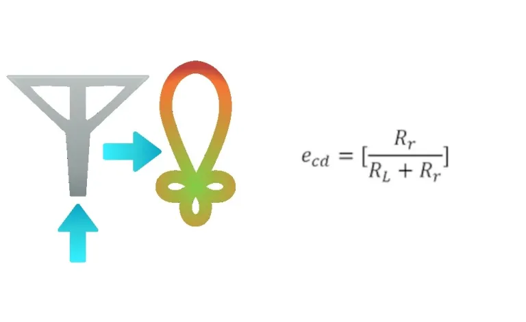
Antenna Radiation Efficiency Tool
Total antenna efficiency considers the reflection, conduction and dielectric losses of an antenna. The dielectric and conduction losses are difficult to compute and therefore often measured. Even with measurements, separation is difficult. The combined losses constitute the radiation efficiency (ecd). The definition of the radiation efficiency is the ratio of the power delivered to the radiation resistance (Rr) to the power delivered to the radiation resistance and the conduction-dielectric resistance (RL)
- ecd = antenna radiation efficiency
- Rr = radiation resistance
- RL = resistance representing the combination of the conduction-dielectric losses.
Antenna Temperature Calculator
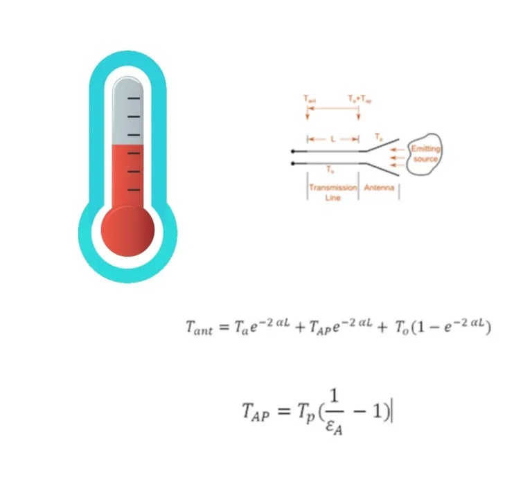
Every object with a physical temperature above absolute zero radiates energy. The equivalent temperature represents the amount of energy radiated.
If an antenna maintained at a certain physical temperature (Tp) is connected to a receiver by a length of transmission line (L), with a constant temperature (To) throughout, and having uniform attenuation (α), the effective antenna temperature at the receiver terminal Tant considering the physical temperature TAP can be calculated.
The parameters used in the equation are:
- Tant = antenna temperature at the receiver terminals (K)
- Ta = antenna noise temperature at the antenna terminals (K)
- TAP = antenna temperature at the antenna terminals due to physical temperature (K)
- Tp = antenna physical temperature (K)
- α = attenuation coefficient of transmission line (Np/m)
- εA = thermal efficiency of the antenna
- L = length of the transmission line (m)
- To = physical temperature of the transmission line (K)
Realized Gain Calculator
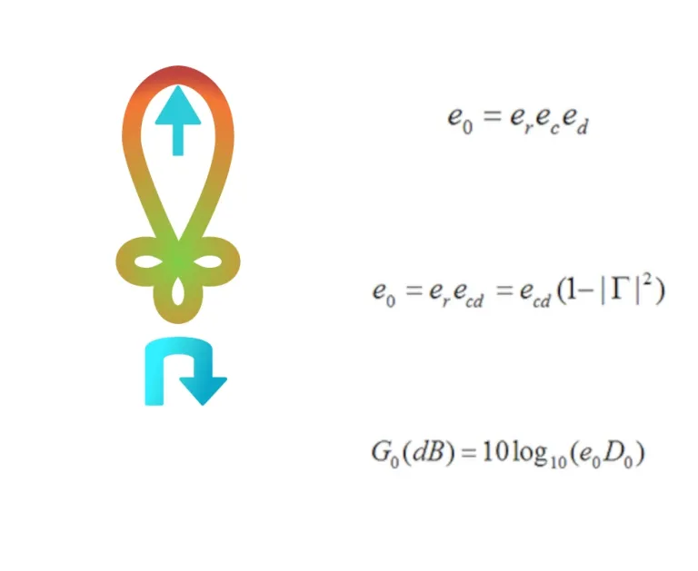
The realized gain of an antenna is calculated by considering the total efficiency of the antenna, along with its directivity.
The total efficiency of the antenna considers the losses due to reflections at the input terminals and losses within the structure of the antenna.
Total efficiency e0 can be written as:
where er is the reflection (mismatch) efficiency, ed the dielectric efficiency and ec the conduction efficiency. The dielectric and conduction efficiencies are usually grouped, since they are measured as one entity, and known as ecd. We can write total efficiency as:
We calculate the realized gain using the total efficiency and the directivity as follows:
Realized gain and directivity are specified in dBi, the voltage reflection coefficient in dB, and the efficiency as a value between 0 and 1.
Aperture Distribution Calculator
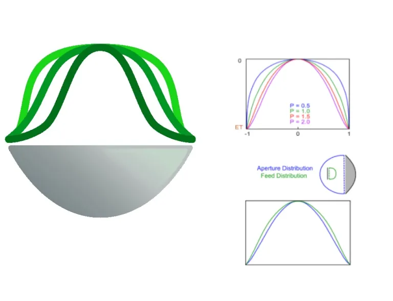
This calculator plots the approximate aperture and feed distribution of a typical axisymmetric parabolic reflector topology. The feed / aperture distribution is determined based on:
- The shape modifier (P) derived for the given focal length to
- The diameter ratio (F/D),
- Edge taper (ET) and
- Aperture / feed distribution efficiency (ade / fde) [Rahmat-Samii].
This image shows the effect of shape modifier P on the feed / aperture distribution:
The distribution at the feed is different from the distribution at the aperture, due to the properties of the main reflector. The graph depends on the F/D ratio of the dish. The aperture or feed efficiency is calculated relative to an 'ideal' flat distribution.
Pattern Approximation Tool
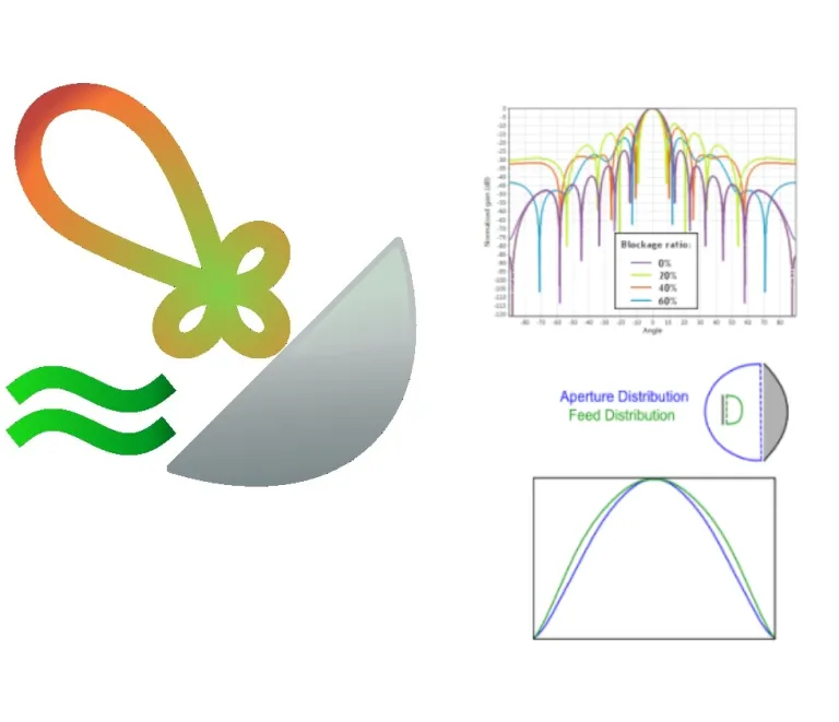
For a specific parabolic reflector dish and feed antenna, we calculate the gain pattern using the handy Pattern Approximation Tool. This tool allows the user to consider the theoretical gain and pattern performance of larger reflectors, which could result in long simulation times. It also enables the prediction of the influence of parameters like blockage ratio or feed distribution efficiency.
For example, we use the tool to study the effect of blockage ratio on the pattern without having to do any simulations, as shown in the graph.
We keep the following parameters constant:
- Operating frequency: 10 GHz
- D (Reflector diameter): 200 mm
- F/D ratio: 0.34
- ET (edge taper distribution): -35 dB
- Fde (feed distribution efficiency): 70%
The distribution at the feed is different from the distribution at the aperture, due to the properties of the main reflector. The graph depends on the F/D ratio of the dish. The aperture or feed efficiency is calculated relative to an 'ideal' flat distribution.
Radar Cross-Section Calculator
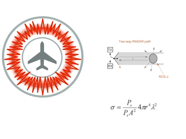
The Radar Cross Section (RCS) of an object is its effective area intercepting the incident power density, which when scattered isotropically would result in the received backscatter power. The estimation assumes that the polarizations are matched.
This calculator returns the Radar Cross Section (RCS) of an object, given various input objectives.
The simplified equation in this calculator determines the RCS of an object, given the frequency, received power, transmitted power, total path distance and antenna aperture area.
An antenna is an object with a unique RCS characteristic, since part of the power received is delivered to the antenna terminals. A good impedance match to the signal reduces the reradiation, and hence the RCS.
Skin Depth Calculator
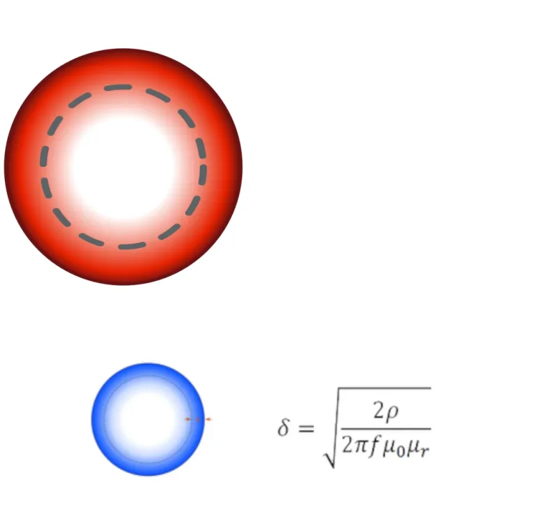
Skin depth is a measure of electrical conduction within a conductor. At DC (0 Hz) the current is equally distributed over the cross section of a conductor. As the frequency increases, the current distribution changes with the highest current density near the surface of the conductor.
Skin depth, δ, is a function of frequency, the conductor's relative permeability, μr, and resistivity, ρ (or conductivity, ο, where ο = 1/ ρ). It is defined as the depth below the surface of a conductor where the current density has fallen to 1/e (≈ 0.37) of the current density at the surface.
Where
δ: Skin depth [m]
μ0: Vacuum permeability [H.m-1]
ρ: Resistivity [Ω.m]
ο: Conductivity [S.m-1]
Also Discover
Learn What SIMULIA Can Do for You
Speak with a SIMULIA expert to learn how our solutions enable seamless collaboration and sustainable innovation at organizations of every size.
Get Started
Courses and classes are available for students, academia, professionals and companies. Find the right SIMULIA training for you.
Get Help
Find information on software & hardware certification, software downloads, user documentation, support contact and services offering

