CATIA
CATIA è la soluzione leader per supportare interi processi di innovazione e sviluppo, per ideare, progettare e simulare nuovi prodotti e sistemi. Consente di creare esperienze di grande impatto per i clienti contribuendo ad un mondo più sostenibile.
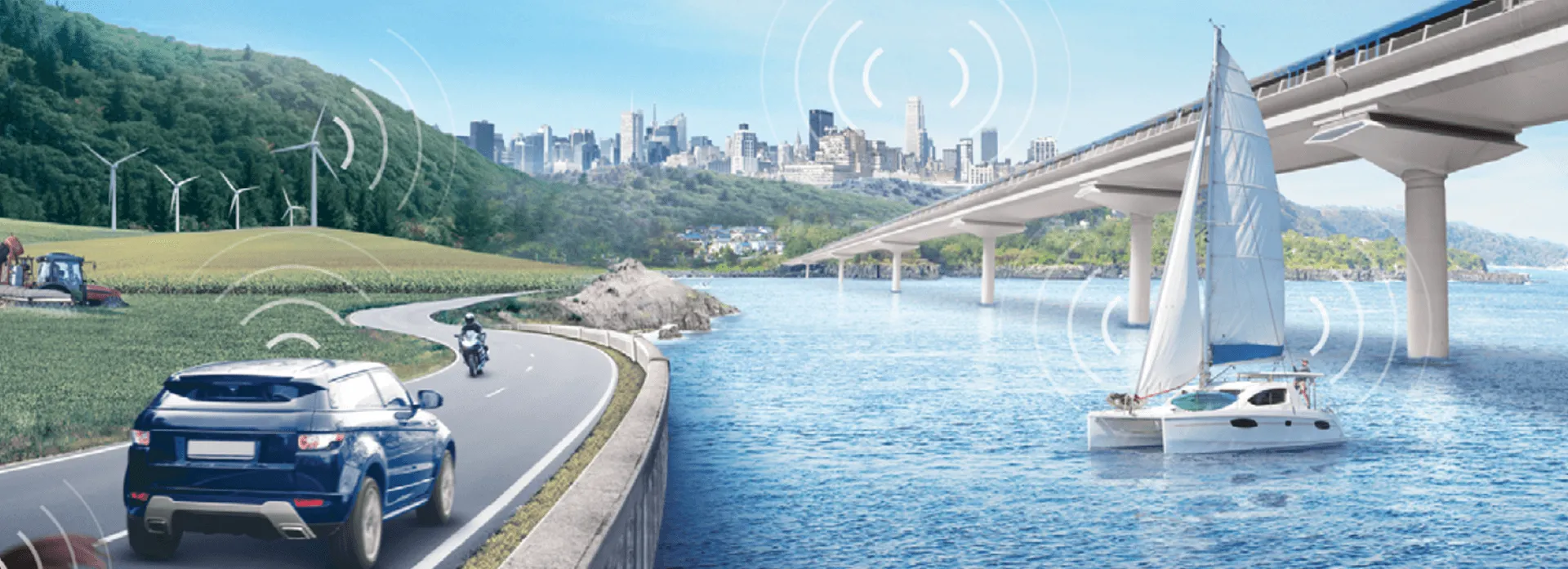
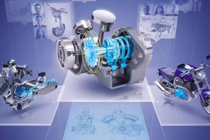
CATIA trasforma le tradizionali aspettative del CAD 3D (Computer‑Aided Design) in una progettazione cognitiva aumentata, che unisce modellazione e simulazione. Sfruttando conoscenze, know‑how e tecnologie collaudate per automatizzare la progettazione e l'ingegneria dei sistemi, CATIA contribuisce a creare un mondo connesso offrendo tutte le funzionalità per la progettazione di esperienze e oggetti connessi basata su sistemi informatici.
CATIA offre un'esperienza utente intuitiva, basata su 3D, servizi Web e tecnologie di realtà aumentata e mobile. CATIA infine consente alle community social di innovatori di collaborare virtualmente e di co-progettare esperienze innovative. Infine, grazie alle funzionalità di modellazione e simulazione di sistemi ciberfisici, CATIA è parte integrante delle soluzioni di settore basate su 3DEXPERIENCE per l'ingegneria di sistemi basata su modelli, l'architettura aziendale, la modellazione di concept e le ontologie. Queste soluzioni consentono ai leader globali del settore di sviluppare l'Internet of Experiences, l'esperienza virtuale intelligente e autonoma che connette digitalmente prodotti, natura e vita nel mondo reale.
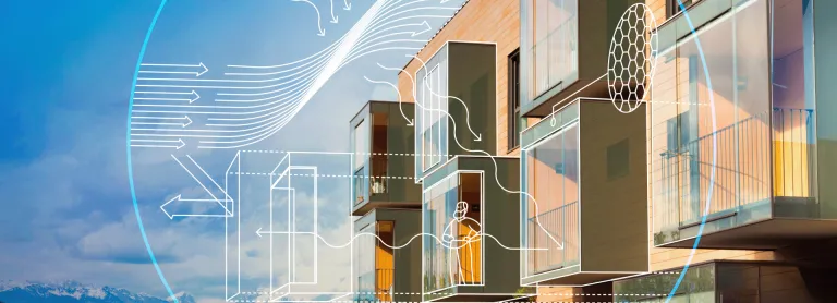
Soluzioni software BIM (Building Information Management) di livello mondiale per architetti, ingegneri civili e appaltatori in tutte le fasi di progetto e attività commerciali.
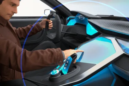
Soluzione unificata di design industriale per il flusso di lavoro
Una serie completa di ruoli ingegneristici integrati in un processo di progettazione in continuità digitale
Permette di sviluppare rapidamente prodotti meccanici di alta qualità
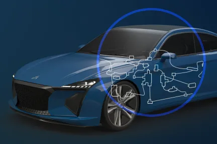
Soluzioni end-to-end basate su modelli per meccatronica ed esperienze basate su software
Portfolio CATIA
Esplora il software e le soluzioni
Temi in primo piano
Scopri il mondo di CATIA
Trai il massimo vantaggio dalla Knowledge-Based Engineering con l’IA
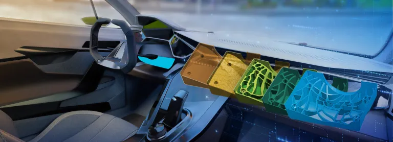
Ottimizza la progettazione con MODSIM (modellazione e simulazione)
Avvia e convalida il progetto di infrastruttura in modo rapido e sicuro
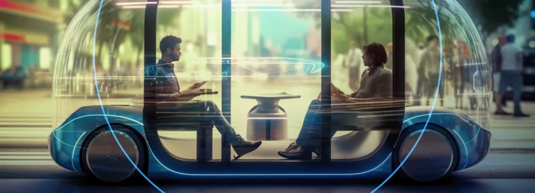
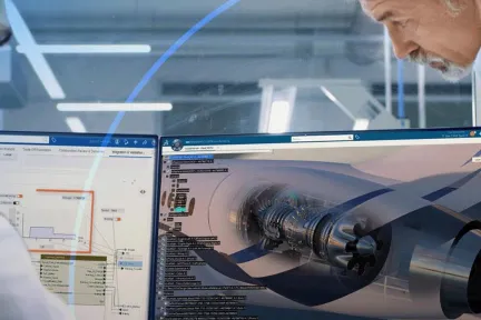
Supera le sfide della trasformazione con soluzioni all'avanguardia per l'ingegneria dei sistemi
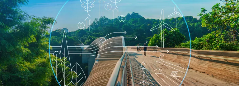
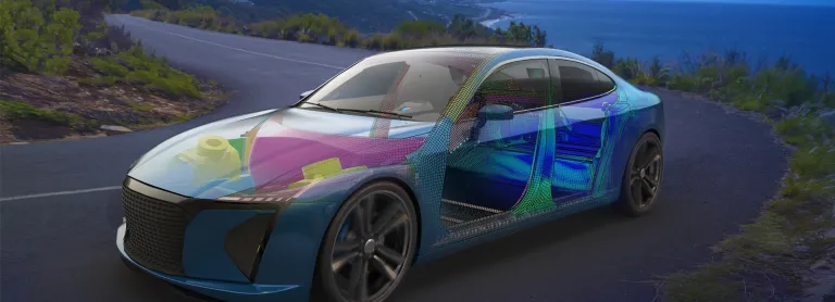
Riduci l'impatto ambientale attraverso la progettazione sostenibile
Testimonianze dei clienti
Scopri in che modo importanti aziende utilizzano le nostre soluzioni di progettazione e ingegneria
Helix
Le trasmissioni elettriche di nuova generazione
Lo sviluppatore di trasmissioni elettriche Helix ha infranto i record e ha vinto premi per i suoi motori elettrici e inverter ad alte prestazioni. 3DEXPERIENCE promuove miglioramenti continui per realizzare progetti ottimizzati e snellire il processo di progettazione dal concept alla produzione.
3DEXPERIENCE è al centro di tutto ciò che facciamo in termini di progettazione e poi di produzione.

Novità e offerte
Blog
Leggi il blog CATIA per conoscere le novità e le innovazioni dei nostri esperti.
Community di utenti
Risorse CATIA essenziali e coinvolgimento attivo con gli altri utenti
Community CATIA Champions
Il programma CATIA User Champion è una rete esclusiva di utenti CATIA esperti e top ambassador. L'utente Champion ideale è altamente qualificato in una o più soluzioni CATIA, oppure gestisce un team di utenti e comprende i vantaggi, le strategie e l'utilizzo di 3DEXPERIENCE CATIA e altri prodotti del portfolio CATIA.
Eventi ed eSeminar
E-book, white paper e altre risorse
Domande frequenti su modellazione 3D e software CAD
Connettiti con CATIA
Scopri cosa possono fare per te le soluzioni CATIA
Parla con un esperto CATIA per scoprire in che modo le nostre soluzioni consentono a organizzazioni di ogni dimensione di ottimizzare la collaborazione e promuovere un'innovazione sostenibile.
Per iniziare
Sono disponibili corsi e lezioni per studenti, accademici, professionisti e aziende. Trova il corso di formazione CATIA più adatto alle tue esigenze.
Ottieni assistenza
Trova informazioni sulle certificazioni software e hardware, scarica software e documentazione per gli utenti, contatta l'assistenza e scopri le offerte di servizi